Password Based Circuit Breaker is a basic project that helps in controlling the electrical lines with the assistance of a secret word.
These days, electrical mishaps to the line man are expanding, while at the same time fixing the electrical lines because of the absence of correspondence between the electrical substation and support staff. This project gives an answer for this issue to guarantee line man security. In this proposed framework, the control (ON/OFF) of the electrical lines lies with line man. This task is orchestrated so that upkeep staff or line man needs to enter the secret word to ON/OFF the electrical line.
Presently, on the off chance that there is any blame in electrical line, at that point the line man will turn off the power supply to the line by entering secret phrase and serenely fix the electrical line, and subsequent to going to the substation line man switch on the supply to the specific line by entering the secret key. Separate passwords are appointed for each electrical lines.
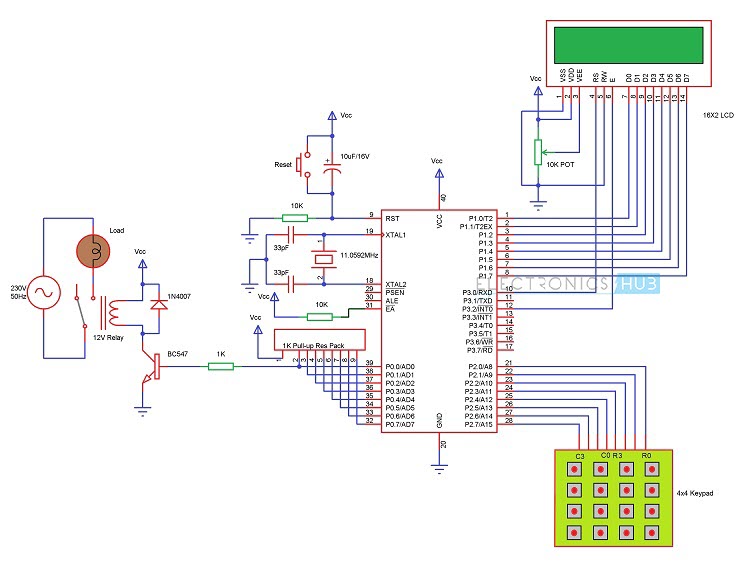
Circuit Diagram of Password based Circuit Breaker

Components Required
- 8051 Microcontroller (AT89C52)
- 8051 Development Board
- 8051 Programming Board (Programmer)
- 4 x 4 Matrix Keypad
- 4 – Channel Relay Module
- 16 x 2 LCD Display
- 10KΩ Potentiometer
- 4 Loads (Light Bulbs)
- Power Supply
- Connecting Wires
- If 8051 Development Board is not used, then you need
- 0592 MHz Crystal
- 2 x 33pF Capacitor
- 2 x 10KΩ Resistors (1/4 Watt)
- Push Button
- 10µF Capacitor (Electrolytic)
- 1KΩ x 8 Pull – up Resistor Pack
- If Relay Module is not used, then you need (components mentioned for one load)
- 5V or 12V Relay
- 1KΩ Resistor (1/4 Watt)
- BC547 NPN Transistor
- 1N4007 PN Junction Diode


0 Comments